Breadboards
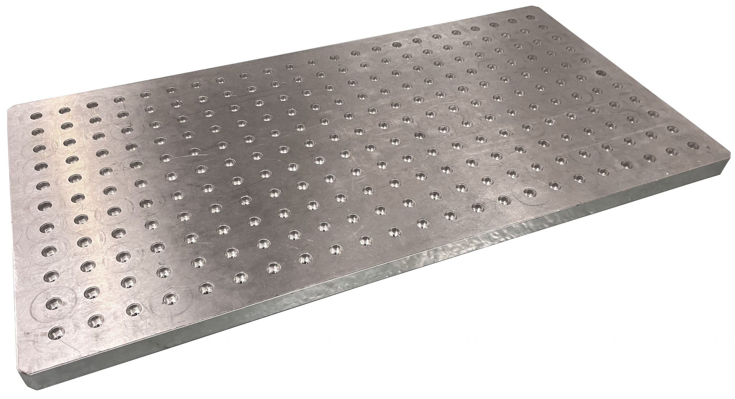
NSRL makes extensive use of standard optical “breadboards” as mounting surfaces for samples and sample-holding fixtures. These are 0.75-inch (1.905 cm) thick aluminum plates with a 1-inch (2.54cm) square pitch grid of threaded mounting holes across their surfaces. The holes are 1/4-20 threaded and have 7/16-inch (11.11 mm) diameter, 0.25-inch (6.35mm) counterbores to accommodate mounting screw heads and allow them to sit flush with the surface.
The figure below is a simplified dimensional drawing of the most frequently used “24×12” breadboard.

Several 18×12, 12×12, and 6×12 breadboards are also available to use and have the same grid pitch and hole dimensions as the 24×12 breadboard.
Most of the NSRL beamline equipment that does mount directly to the rails has been designed to interface with this type of breadboard.
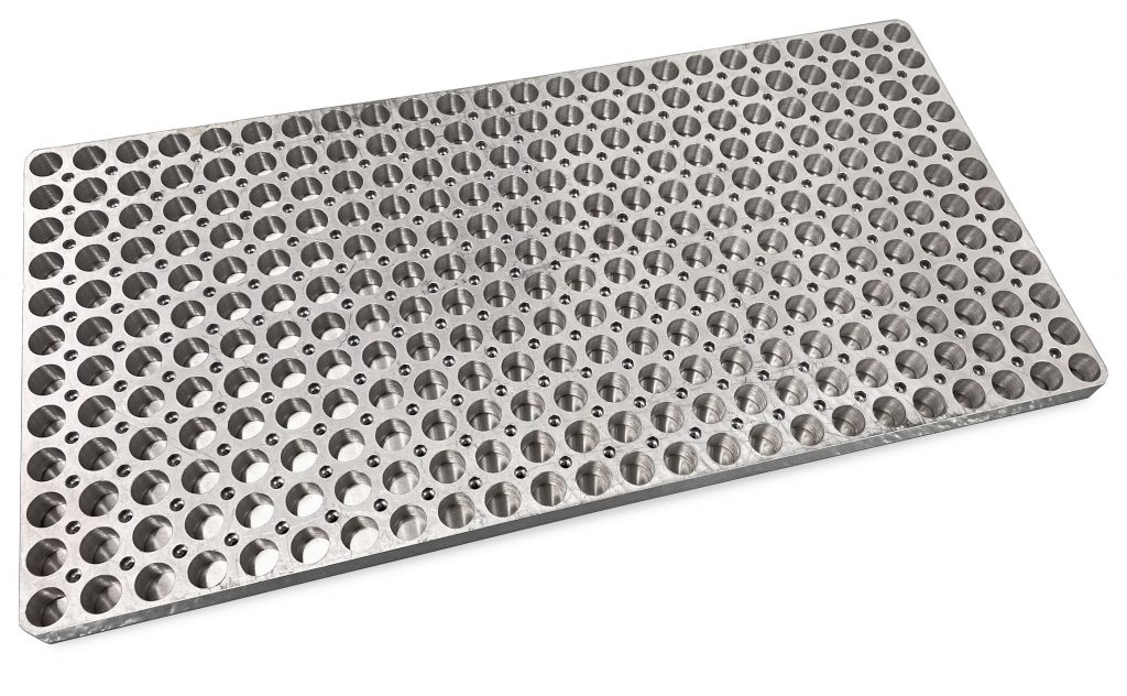
Some breadboards have had many holes drilled out of their undersides so as to reduce their weight. The image to the left shows a lightweight 24×12 breadboard.
Vertical Translation Stage
Breadboards supporting experimental apparatuses or other equipment can mounted to the rail system through the use of a height-adjustable stage. This vertical translation stage can be operated locally or remotely, and can be positioned at any point along the rail system. Its top surface sits 1 inch (25 mm) above the top of the rails at the lowest, and can extend with a total of 8.75 inches (222 mm) of travel up to 9.75 inches (248 mm) above the top of the tails.
The 10x speed video below depicts the vertical translation stage being remotely driven between its lowest and highest positions.
Horizontal Translation Stage
An additional horizontal translation stage is almost always added to the vertical translation stage to give it the functionality to be adjusted in the horizontal axis. The horizontal translation stage is bolted directly to the top surface of the vertical stage, adding an additional 2.75 inches (70 mm) of height.
The stage has a total travel range of 16.0 inches (40.6 cm) and, like the vertical stage, can be operated either locally or remotely.
The 10x speed video below depicts the operation of the horizontal translation stage atop the vertical translation stage. The stages are driven remotely to translate on both the horizontal and vertical axes.
The use of the combined vertical and horizontal translation stages is the primary method by which test articles are aligned with the beam.
Vertical Clearance
One of the most common issues for electronics testing experiment setups is the lack of sufficient vertical clearance. Because test articles are almost universally mounted on breadboards which are themselves mounted on the horizontal and vertical translation stages, there is generally a minimum of only 8.47 inches (21.5 cm) of distance between the breadboard’s top surface and the center of the beam.
The two figures below depict a cross sectional view of the translation stages positions relative to the beam at either extent of the vertical stage’s travel.
On the left, a cross sectional view of the rail system is shown. A cartoon of a 20×20 cm2 beam spot is shown in red, with the positions of the uniform areas for both a 20×20 cm2 beam and a 7×7 cm2 beam shown as solid black outlined squares. The vertical translation stage, horizontal translation stage, and standard optical breadboard are depicted in green, blue, and yellow respectively. The right diagram shows the same components but with the vertical translation stage at its maximally extended position.
Users should ensure their test apparatus is low enough that it can centered in the beam when mounted on a breadboard and both translation stages, or otherwise inform NSRL staff well ahead of time about the use of an alternate mounting option such as the lower rails.
4-foot Horizontal Translation Stage
While not often used for electronics testing experiments, there is a longer horizontal translation stage which can be used if samples are lightweight and do not need many monitoring cables. This stage—sometimes referred to as the “4-foot table”—is a specialized version of the standard horizontal translation stage: essentially identical except that it has 40 inches (101.6 cm) of horizontal travel.
The table is, like the standard horizontal stage, used in conjunction with a vertical translation stage. In order to make effective use of the increased travel distance, it most often is used with a special 0.5 inch (1.27 cm) thick 48×12 extended breadboard. The extended breadboard uses 1/4-20 threaded holes but has countersinks instead of counterbores.
Because the stage’s movement is not counterweighted, items must be arranged on the breadboard such that the stage does not tip at either extreme of travel. This along with its large size makes it cumbersome to work with, so it should only be used if there is a compelling reason to do so.
[picture of 4-foot table]
This page was last modified: