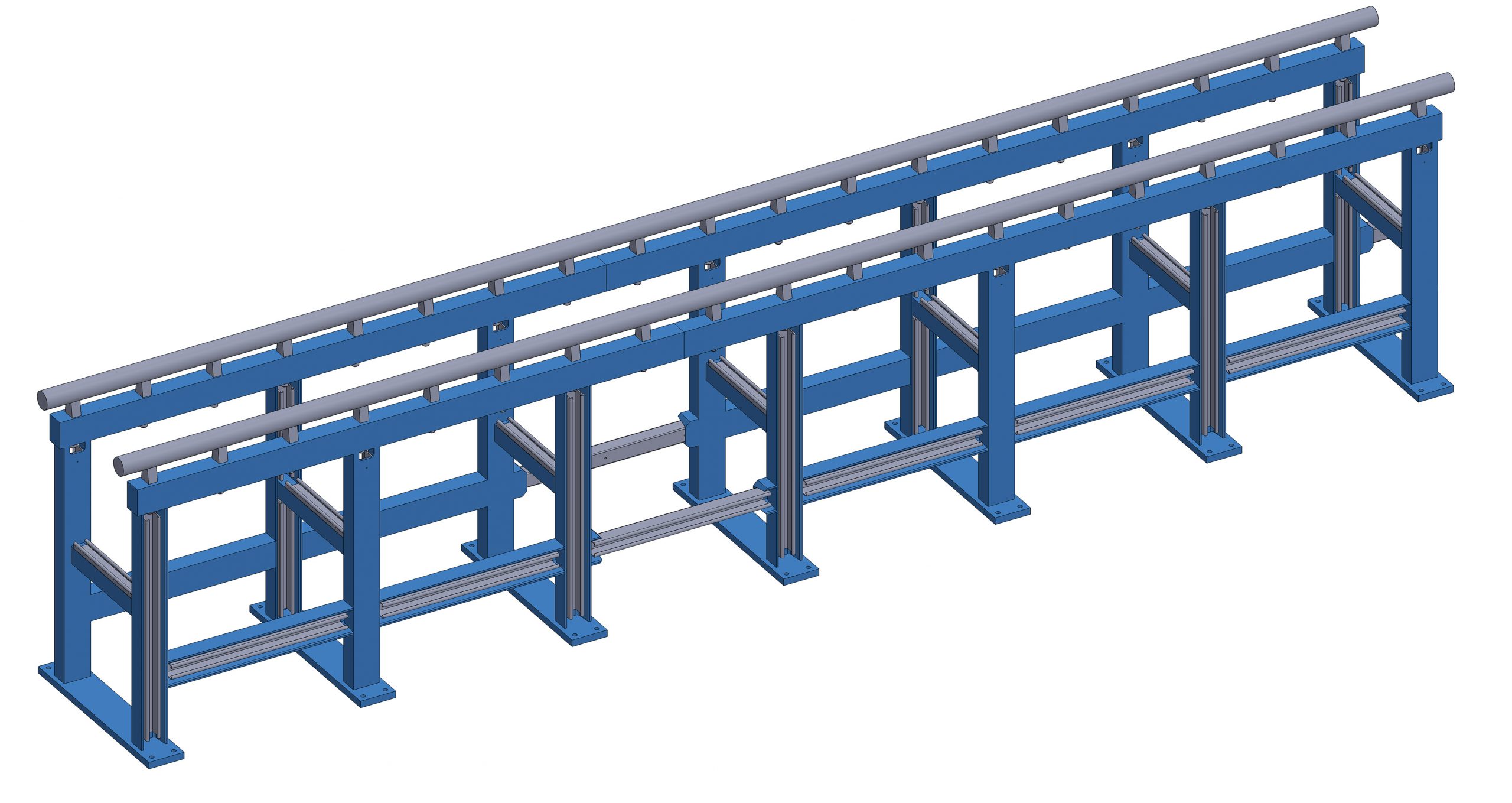
Beamline components are installed in, mounted to, or placed atop a rail system that runs below the axis of the beam. It consists of a pair of 2.00 inch (5.08 cm) diameter stainless steel rails spaced 15.0 inches (38.1 cm) apart between their centers supported by several sections of steel frame. A view of a simple 3D model of one section of rail system is shown below.
The top surface of the rails sits 13.0 inches (33.0 cm) below the center of the beam. The rail system itself is nominally 35 inches (89 cm) tall, however its exact height is not the same everywhere due to variations in the height of the target room floor.
The figure below is a simplified dimensional drawing of the rail system as viewed from the front.

The beam center position is denoted by crosshairs. The space within the frame between the rails is occupied by several instrumentation cable trays, however there exists a 13.25 inch (33.66 cm) wide by approximately 13 inch (33 cm) deep clearance section to permit equipment that partially or completely hangs beneath the rails. For example, the vertical translation stage is supported by the rails while its lift mechanism sits beneath them.
The figure below is a diagram of the rail system as viewed from the beam-left (west) side. You may need to download the image and zoom in if the dimensions are too difficult to read.

The beam travels from the right of the diagram to the left and is represented by a dotted line. The scale below shows the distance from the vacuum window in both inches and centimeters.
The vast majority of physics and electronics testing experiments are conducted towards the upstream end of the rails. As such, a nominal “Z-axis” position at 38.0 inches (96.5 cm) downstream of the vacuum window was defined as the upstream testing position. Unless specifically requested otherwise, reported beam energies are calibrated for the upstream test position.
While most of the rail structure is fixed in place, some small sections can be removed to permit the installation of large experimental apparatuses. These sections are on casters rather than being bolted directly to the floor, and are labeled on the above diagram.
Some rail sections which are not directly supported by frames below can also be removed to permit additional clearance for equipment. Without rails, however, equipment will need to be supported from the floor and not interfere with the lower section of the frames as well as cable trays.
Patch panels and electrical outlets available for use by experimenters are mounted to the rail system at many positions along its length.
Lower Rails
The removable section of rail system that sits directly beneath the upstream test position has an additional set of rails—with the same diameter and between center spacing—that sit below the main rails. This additional set of rails, often called the “lower rails”, are height adjustable and can permit the use of experimental setups that require more vertical clearance than can be achieved using the main rails, while still allowing for the use of standard rail-based mounting equipment like the translation stages.
Experimenters should be cognizant of the 26 inch (66 cm) clearance length limit to the lower rails assembly, as well as the additional time required by NSRL staff to prepare the lower rails for use. If experimenters discover that they will not have enough vertical clearance with the main rails after setting up and decide to switch to the lower rails, they will likely need to partially or completely disassemble their apparatus and reassemble it once the lower rails are prepared.
This page was last modified: