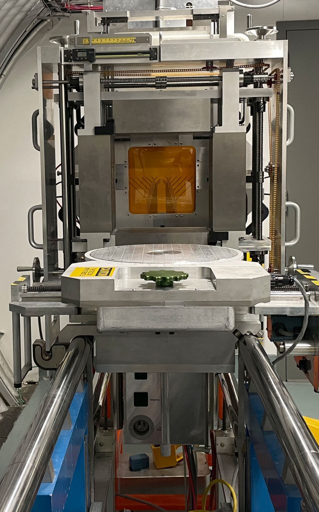
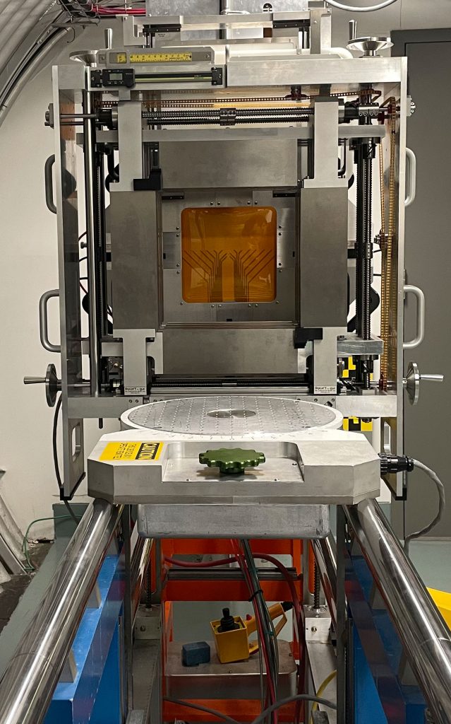
Experimenters may make use of a rotation table that can be centered on the beam line and be remotely adjusted to align samples at any angle with respect to the beam. The surface of the table is covered with 1/4-20 threaded holes in a 1-inch (2.54 cm) pitch square grid, much like the breadboards but without the counterbores.
The 5x speed video below shows the rotation table in action.
The central 9 holes are fixed and do not rotate with the table. They are located in a circular section that sits 0.125 inches (3.18 mm) below the level of the rest of the holes to allow for things to be placed over them without interfering with the table’s rotation.
The figure below is a simplified dimensional drawing of rotation table viewed from above.

When needed, the rotation table is most often affixed to the top of the horizontal translation stage (which itself sits atop the vertical translation stage). However, if additional vertical clearance is required, it can also be affixed to just the vertical translation stage or sit directly on the rails. The images below show these three options at their lowest positions respectively.

The diagram below depicts a cross sectional view of the three aforementioned mounting methods with dimensions labeled.
Three cross sectional views of the rail system are shown which depict, from left to right, mounting the rotation table to both the horizontal and vertical translation stages, mounting it to just the vertical translation stage, and mounting it to the rails directly. A cartoon of the 20×20 cm2 beam spot is shown in red, with the positions of the uniform areas for both a 20×20 cm2 and 7×7 cm2 beam spot shown as solid black outlined squares. The vertical translation stage, horizontal translation stage, and rotation table are depicted in green, blue, and yellow respectively.
This page was last modified: