Target Room Electrical Outlets
There are many electrical outlets distributed throughout the target room for use by experimenters. They are located along the length and on either side of the rails, as well as around the perimeter of the target room.
The majority of outlets are standard 120V, 20A receptacles and use NEMA 5-20R connectors. Many of these have isolated ground connections, a feature that is denoted with by their orange color and “∇” symbol label.
In addition, there are 2 outlets which can provide 208V (single phase) power at up to 20A. Both outlets use NEMA 6-20R receptacles.
For high power needs, there are also 2 outlets which provide 3-phase (“wye”) 120/208V power, each with their own set of 30A breakers.
The figure below is a simplified floor plan map of the target room showing the location of all electrical outlets. You may need to download the image and zoom in in order to read the small text.

Some outlets appear in a light gray color, indicates that are generally not available for use by experimenters, as they are currently being used to power NSRL equipment.
Please note that one of the outlets near to the upstream testing position of the beamline does not share the same ground reference as the other outlets in the target room. Users are welcome to use this outlet but should be cognizant of the effects of any ground loops on their test setups.
Remotely Switchable Outlets
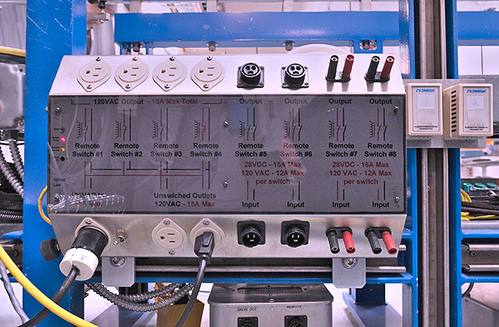
A switchable outlet system is installed on the rails which provides 4 NEMA 5-15R receptacles that can be independently switched on and off from outside the target room. The outlets can be controlled from a simple graphical interface running on the user computer. A photo of the system is shown below.
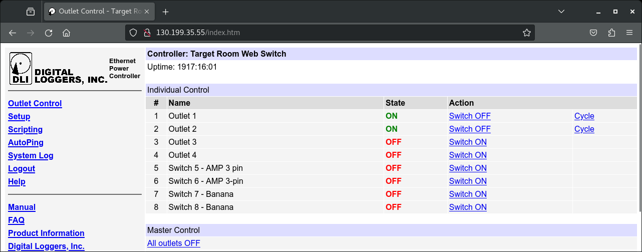
A screenshot of the graphical interface that can be used to control the system is shown below.
There are 2 additional un-switched outlets provided by the system which also use NEMA 5-15R receptacles.
The total current draw for all outlets—both switchable and un-switchable—on the system is limited to 15A.
The system is located at a point approximately 10 feet (3 meters) downstream of the electronics testing position.
In addition to the outlets, there are also 4 pairs of connectors that can be switched via relays, allowing for remote control of user-supplied power if they choose to route it through the system.
There are 2 sets of standard banana jack pairs, controlled by switch #7 and switch #8. The provided power can be either AC or DC, and is limited to 28VDC at a maximum of 16A or 120VAC at a maximum of 12A per switch.
There are also 2 twist lock three-conductor power connector sets controlled by switch #5 and switch #6. They are all TE Connectivity AMP 17-3 connectors—206043-1 for the input receptacles and 206037-2 for the output plugs. Each of these switches is limited to 28VDC at a maximum of 15A, or 120VAC at a maximum of 12A.
Experimenters should be cognizant of any cable length limitations if they decide to use the system to switch their own power due to the potentially large distance between its position along the rail relative to the standard upstream testing position.
This page was last modified: