- RHIC Magnets (Papers, Presentations, Notes)
Relativistic Heavy Ion Collider (RHIC) at the Brookhaven National Laboratory (BNL) is the first accelerator consisting of all and only superconducting magnets. It was built after the successful construction of Tevatron and HERA, whose main dipole magnets were also superconducting having similar aperture (Tevatron:76.2 mm, HERA:75 mm, RHIC:80 mm). RHIC magnet development benefited from the experiences of Colliding Beam Accelerator (CBA) or ISABELLE (the Intersecting Storage Accelerator + “belle”) and Superconducting Supercollider Collider (SSC) projects. Even though these later projects were not completed, they contributed significantly to the design of RHIC magnets.
Several types of superconducting magnets were developed for RHIC. In main ring and interaction region magnets, the magnetic designs were pushed to the next level utilizing several approaches which were new at that time but became standard in other magnet programs that followed. This was done either to reduce the cost of the program and/or the number of prototypes to be built (or eliminated). This was done while maintaining a field quality during a large production and/or to achieve a high field quality which was never required before. It may be mentioned that the good field quality in RHIC magnets was not achieved by increasing the tolerances in parts (which typically causes increase in cost and delay in schedule), but by developing a better understanding of the impact of errors in individual parts and by developing techniques to accommodate out of tolerance parts. In fact, hardly any part was ever rejected that helped maintaining the schedule. For example, phenolic spacers used in RHIC magnets had several times more error than the stainless-steel (SS) collars used in other magnets, but still field errors in RHIC magnets were smaller than in other magnet productions.
Major highlights of the techniques developed during the R&D phase that played a key role in the success of high quality RHIC magnets are:
- Techniques developed brought a large reduction in field errors due to non-linear iron saturation in the operating range despite a large contribution to the total field from iron.
- Techniques developed to keep field errors in RHIC arc (main) dipole small, well beyond the maximum design field to quench field (>30% over the design field). This is important for upgrading the RHIC facility for the Electron Ion Collider (EIC), where these magnets must be used at higher fields.
- Techniques developed for building good field quality magnets without the expensive and time-consuming prototype magnets.
- Techniques developed to maintain a good field quality in large scale production despite the variation in parts and assembly without requiring any change in coil or yoke cross-section.
- Techniques developed for reducing field errors beyond what was possible from the nominal tolerance in parts and assembly.
- Techniques developed to build magnets which are less prone to assembly errors.
- Techniques developed to use field harmonics as a tool to monitor magnet production and to discover major and/or minor faults in magnet construction.
- These techniques demonstrated that the field quality in the series production of RHIC dipoles was significantly better than similar aperture magnets built for other accelerators (RHIC 80 mm, Tevatron 76.2 mm and HERA 75 mm) throughout the operating range.
Iron yoke and field quality at high fields in RHIC Main Dipoles:
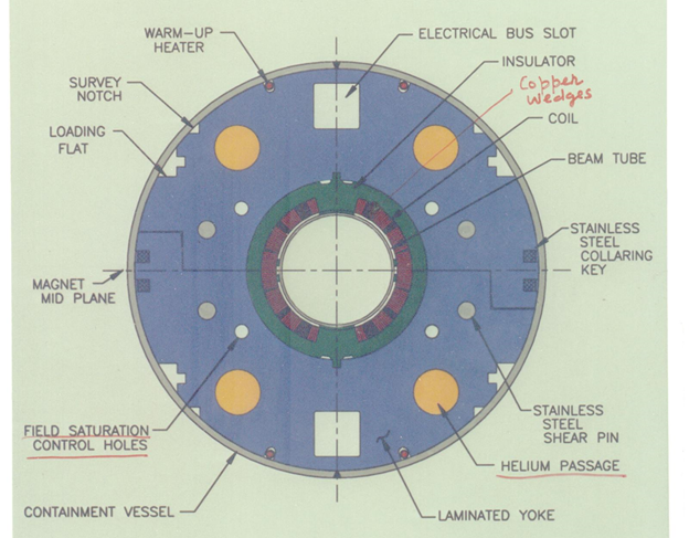
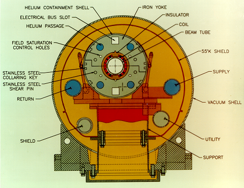
RHIC 80 mm aperture arc dipole coldmass. The location and material of the keys and the shear pins are optimized, along with the location and size of the saturation control hole, and the location of Helium hole to control the field harmonics as a function of field.

In most RHIC magnets, the iron yoke serves as the primary support structure (collars) and is brought very close to the coil. This significantly reduces the cost and increases the contribution of the field from the iron. In fact, in RHIC dipole the contributes of field from the iron is about 50% of the coil field. This, as per the conventional thinking, comes at a cost of a deterioration of field quality due to the non-linear iron properties quality at high fields. This in fact was observed in the initial designs (see figure below). Techniques were developed where this penalty (seen as the change in field quality as a function of current) was overcome. Figure below shows the change in sextupole and decapole harmonics as a function of current in long R&D dipole magnets built and tested for RHIC over a decade. Please note that an offset is used in each dipole magnet to make the sextupole or decapole harmonic in each magnet starts from zero at 2 kA and an average of up and down ramp is used to minimize the impact of persistent currents.
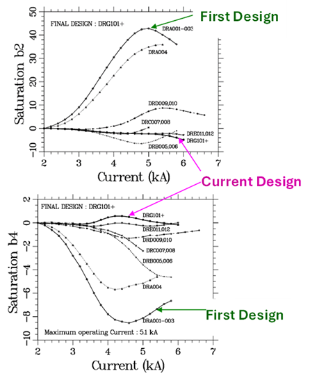
Variation of sextupole and decapole field harmonics as function of current in RHIC 80 mm aperture arc dipole at a reference radius of 25 mm.
This dramatic improvement was obtained by a fundamental change in thinking on how yoke iron should be designed. Field harmonics change because the magnetization in yoke becomes non-linear as function of field beyond ~1 T and the magnitude of the field in yoke across the iron yoke. The conventional thinking was to reduce the field in the iron and/or keep saturating iron away (for example by increasing the yoke inner radius). However, this also reduces the contribution of the field from the iron and increases the expensive structure material between the coil and the iron. During the RHIC and SSC magnet program, an approach was developed where instead of decreasing the magnitude of the field in the iron, strategically placed holes were used to make it increase where it was low, particularly in the yoke closer to coil which contributes most to the field (see picture below).
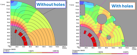
Magnitude of the field and field lines superimposed on a quadrant of the yoke in RHIC 80 mm arc dipole with and without various holes and cutouts – the size and location of holes and cutouts were optimized to control iron saturation.
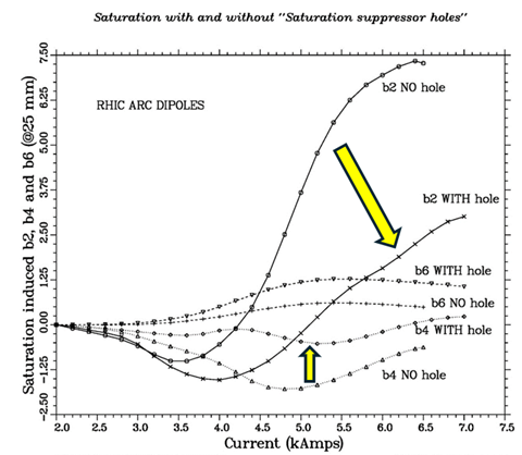
Variation of sextupole and decapole field harmonics as function of current with and without additional saturation control hole in RHIC 80 mm aperture arc dipole at a reference radius of 25 mm.
At a conceptual level, it was driven by an approach that the non-linear saturation of the iron yoke (the basic property of material) can be managed by forcing it to saturate uniformly as a function of azimuth at the yoke inner radius. The outcome was that the current dependence in error harmonics remained low, not only through the design field but also well beyond as well (see picture below). It is very different from the magnets built for previous accelerators (such as Tevatron and HERA), where the field quality deteriorated rapidly after the design field. In fact, it is becoming handy for EIC, where the magnets are going to operate at higher energy.
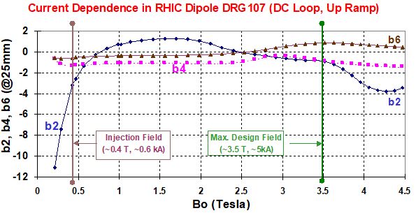
Variation of sextupole (b2) and decapole (b4) and b6 field harmonics at a reference radius of 25 mm, plotted as function of current in the final design of the Industrial production of RHIC 80 mm aperture arc dipole.
It should be acknowledged that, like many other developments, the technique to reduce the saturation-induced harmonics benefited directly from the experience of the magnet program of the Superconducting Super Collider (SSC). The specification for the sextupole harmonic in the SSC dipole magnets was +/- 0.8 unit. This included errors from all sources (including geometric harmonics from the design, parts, and assembly) in addition to that from the iron saturation. In many of the earlier designs of the SSC dipole, the measured current dependence in the sextupole harmonics, as shown below, was itself larger than the overall specification. To help understand and compare the current dependence, an offset is used in each dipole magnet, to make the sextupole harmonic to start from zero at 2 kA in each. Moreover, an average of up and down ramp is used to minimize the impact of persistent currents from 2 kA onward.
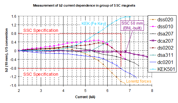
Measured sextupole harmonics (b2) as a function of current in various SSC dipoles at a reference radius of 25 mm.
The above-mentioned approach, was able to make the current dependence in the sextupole harmonic essentially zero (<0.1 unit) through the design current (~6.6 kA), as shown in the figure below for the four 15-meter long 50 mm SSC dipoles (DCA207 through DCA210), built and tested at BNL. As before, an offset is used in each dipole magnet to make the sextupole harmonic in each magnet to start from zero and an average of up and down ramp is used to minimize the impact of persistent currents from ~2 kA to ~7 kA.
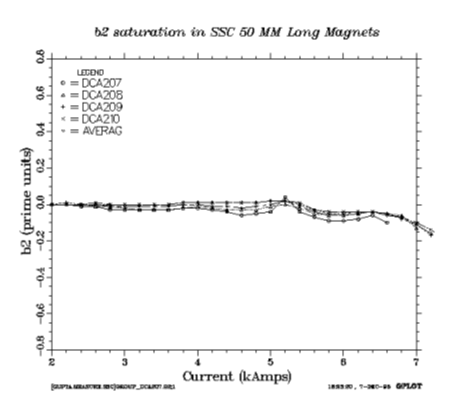
Measured sextupole harmonics (b2) as a function of current in the optimized design used in four 15 meter long SSC 50 mm dipoles at a reference radius of 25 mm.
Techniques developed to reduce skew quadrupole at high fields:
During the R&D phase of dipole magnets for the Superconducting Supercollider (SSC), a variation in the current dependence of skew quarupole harmonic was observed along the magnet length. Skew quadrupole in dipole is the reflection of a top-bottom asymmetry. As shown below, we were able to correlate this to difference between the top and bottom yoke halves in a 50 mm aperture, ~15-meter long dipole magnet DCA213. We were later able to use this observation to benefit the RHIC magnet program.
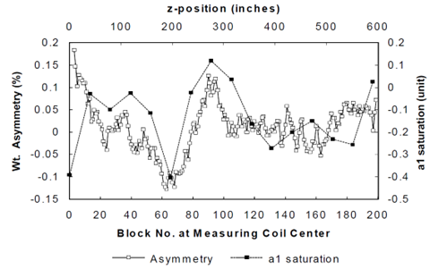
Variation of Top-bottom weight asymmetry and change in skew quad harmonic (da1) along the length of the SSC long dipole magnet DCA213.
RHIC 80 mm aperture arc dipole in the cryostat. Please note off-centered cold-mass in cryostat, the impact of which is observed in field quality at high fields, when the yoke iron is saturated.
During the series construction phase of RHIC dipole magnet at the industry (Northrop-Grumman), a large magnet-to-magnet variation in the current dependence of the skew quadrupole harmonic was observed. We were able to correlate this to the difference in weight between the top-and bottom yoke-halves. Deriving confidence from our work on the SSC dipoles, as explained above, industry was instructed to put heavier packs of yoke halves at the bottom half of the magnet. This resulted in a mid-course improvement (reduction in skew quadrupole harmonic at high field) without causing any practical impact on the industrial production of the magnet. One can see an overall reduction in the saturation induced a1 in the later production of magnets (identified as current magnets in the caption).
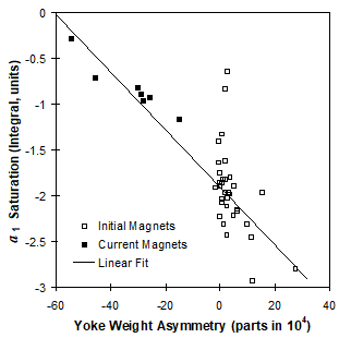
Saturation-induced skew quadrupole harmonic (a1) as a function of top-bottom asymmetry in a number of 80 mm aperture RHIC dipole built in the industry. The weight difference between the top and bottom yoke halves was not used to reduce a1 saturation in the earlier construction.
RHIC dipoles coldmass was bent (have a sagitta) to follow the beam, which otherwise would have caused a loss in magnet aperture. The cryostat was, however, not bent for cost reasons. Therefore, in addition to the skew quadrupole, the placement of the curved coldmass in straight cryostat also produced a variation in normal quadrupole harmonic as a function of axial position in the magnet. This variation was small and acceptable.
Assuring field quality in series magnets and initial magnets without prototyping
Prior to the RHIC magnet production (including the production of prototype of RHIC and SSC magnets), it was deemed necessary that a few magnets are required to assure the required field quality of a few parts in 10,000 in a good field region (typically 2/3 of the coil aperture). This is because of the fact that despite the tight tolerances in parts and construction, the cumulative impact of them exceeds the allowable field errors in harmonics. In RHIC magnets, the specified tolerances in the dimensions of the most crucial parts are typically ±25µm (0.001”). Table below lists the harmonics produced by +25µm error in the three wedges, pole shim and the coil mid-plane gap.
Table: Harmonics produced by +25µm errors.
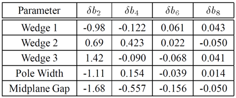
One can see that even though the impact of the allowable error in one part doesn’t exceed the limit, the combination of a few does. The situation is even worse because, in addition, the magnet coils, as manufactured, do not match the ideal coil geometry assumed in the model and also the coil as designed had non-zero harmonic errors. The later errors can be empirically corrected in an iterated design but not in the first magnet itself. In fact, none of the earlier R&D magnets built for RHIC and SSC met the required field quality requirements, before the flexible design approach was implemented.
The flexible design approach and a well thought out plan for accommodating simple mid-course corrections, as needed, to navigate the harmonics stay well within the specifications, without any disruption in industrial production. The results are given in the table below:
Table: The average and RMS values of field harmonics in various cross section designs for RHIC arc dipoles.
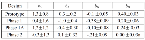
In the table above b2 harmonic is given at the maximum field (3.46 T) and the other harmonics at injection (0.4 Tesla). The measured warm cold correlation of 40 magnets is used to estimate harmonics in 129 magnets measured warm.
Field quality in RHIC, HERA and Tevatron dipoles:
Coincidentally, the main ring dipole magnets for RHIC, HERA and Tevatron had similar coil apertures (RHIC 80 mm, HERA 75 mm, and Tevatron 76.2 mm) and all three were made in large quantities. This offers a unique opportunity to compare field quality in three magnets. S. Peggs and J. Wei (Ref) compared the net field error on the mid-plane in the RHIC dipole magnets with the dipoles in HERA and Tevatron at the design field. One can note the field quality in RHIC magnets, despite the close in saturating iron, significantly better than others.
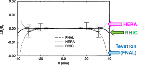
The field error at top operating field on the midplane of the 80 mm aperture RHIC arc dipoles compared with 75 mm aperture HERA and 76.2 mm aperture Tevatron dipoles. The error bars show the RMS variations.
A similar comparison is made at the injection energy in the figure below.
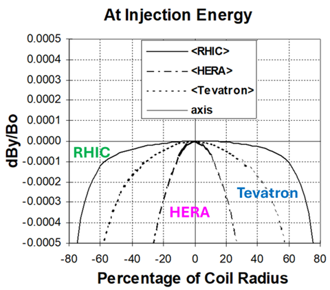
Field error at the midplane of main dipoles of the three major accelerators (RHIC, HERA and Tevatron) at the injection energy.
Finally, the measured harmonics are compared in the following figure:
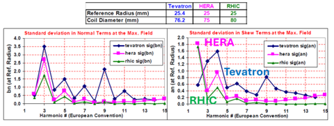
Field harmonics in the main dipoles of the three major accelerators (RHIC, HERA and Tevatron).
RHIC 100 mm aperture insertion dipoles
Whereas, RHIC 80 mm dipole benefited from several R&D and prototype magnets, no such plan was made for the 100 mm aperture insertion (interaction region) dipole D0 (DRZ series dipoles). This was done to reduce the cost to the program, assuming that the two designs can be made very similar. Such a plan had never been considered for any accelerator magnet before.
The flexible design approach developed during the RHIC magnet program allowed us to take the risk of proceeding to start production of series magnets, without building any prototype before and carry out the adjustments/iterations during the construction. In fact, the very first dipole DRZ001, achieved a good field quality in the body of the magnet at a medium field with the desired pre-stress in the first cold test. It followed some adjustments based on warm measurements. Figure below shows the field errors at the midplane at 2kA in the body of the magnet, as computed from the measured harmonics.
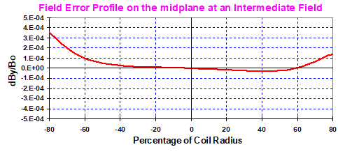
Field error at the midplane in the body of the first 100 mm dipole for the RHIC insertion region at an intermediate field. Please note good field quality in the body of the very first magnet of the production, thanks to a flexible design approach.
The geometric field quality was tuned by increasing the midplane gap and pole shim from the minimum required value. Increasing the midplane gap from the required minimum value was against the basic magnetic design principles at that time. This was because the turns at the midplane are the most efficient in creating field and, therefore, an efficient design would require that to be minimum. However, it was also observed that this (the coil midplane gap) parameter is also the most efficient in tuning field harmonics and hence a slight loss in efficiency was tolerated. Moreover, together with the pole shim, it gave two parameters to tune two harmonics with no change in coil as made.
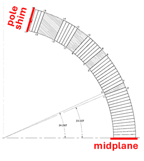
A quadrant of the coil cross-section for the 100 mm aperture RHIC insertion dipole. Adjusting the size of midplane gap and the pole shim gives the ability to tune two harmonics without changing the coil, as built.
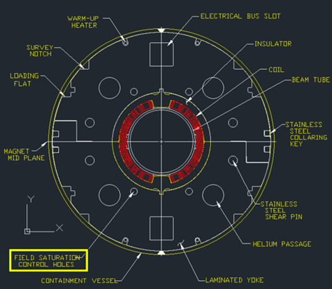
Yoke design of the 100 mm aperture RHIC insertion dipole. Adjusting the size, location and material inside the yoke cutouts provides an ability to control or tune the iron saturation.
The saturation-induced harmonics were tuned by first filling the saturation control holes with the iron rods in the earlier dipoles and removing the saturation control holes entirely from the yoke die of the later dipoles.
Even though the very first 100 mm dipole achieved the good field quality in the body of the magnet at a medium field, integral field quality could not be measured and hence assured at high fields because the required full-length measuring coil was not available in the beginning of the program for cold measurements. Extra high integral field quality at the design field was, however, only required in the two critical high luminosity interaction regions. Therefore, a practical approach was taken to continue iterating the magnetic design through the production as more data and measuring coil becomes available. This strategy allowed us to keep improving the field quality without interrupting the coil or magnet production and hence any delay or increase in the program cost. The figure below shows improvements in field quality during the production of the first eight 100mm RHIC insertion dipoles, as mentioned in a PAC 1997 paper (some data were extrapolated based on measurements from other magnets).
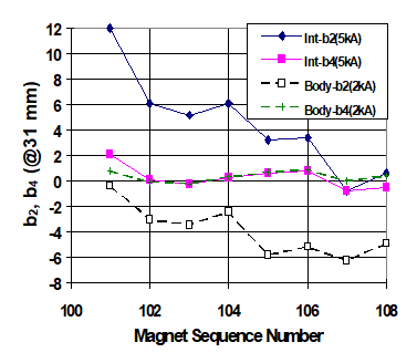
Iteration of sextupole (b2) and decapole (b4) at a reference radius of 31 mm, during the production of the first eight RHIC 100 mm aperture insertion dipole D0 (series DRZ101-DRZ108). Please note a constant improvement in field quality through production without any change in coil cross-section or interruption in production.
Once the design was finalized for good field quality, no more changes were needed, and the design remained fix from the magnet DRZ108 to DRZ125.
Field Errors on the X-axis of 100 mm RHIC insertion dipole D0 (DRZ magnets 108-125) at 3 kA as computed from the measured harmonics (some extrapolated based on the warm-cold correlation). An extra ordinary good field quality may be noted for the 80% of the coil radius.
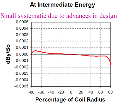
Average field error at the midplane in the body of the 100 mm dipoles (DRZ108-DRZ125) for the RHIC insertion region at an intermediate field, after the design was optimized. Please note very good field quality to 80% of the coil radius.
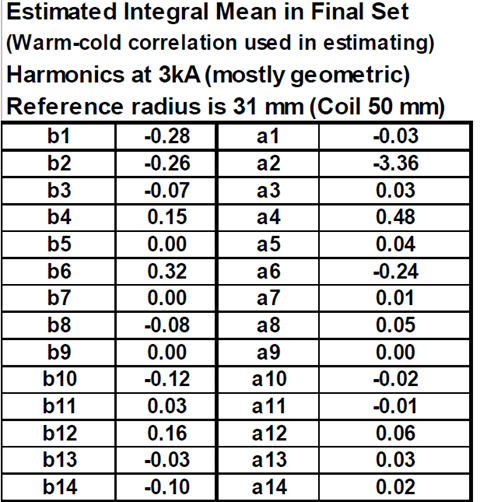
The average or mean value of the integrated field harmonics is given in the table below. All harmonics, except for the a2 (which is coming from the magnet leads and was acceptable), are a few parts in 105, rather than a few parts in104, typical for accelerator magnets.
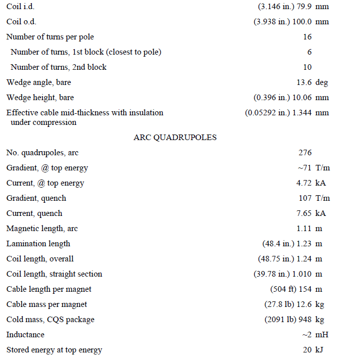
RHIC arc (main) quadrupoles
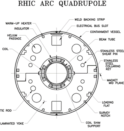
Like arc dipole magnets, quadrupole also uses iron as collar as a part of making a low-cost design. To further reduce cost, these quadrupoles (4-fold symmetry) are assembled/collared like dipoles (2-fold symmetry), even though this is something which is not desired in an ideal design. To implement this, the relevant features of the quadrupole yoke and the collaring process were made similar to the dipole yoke (see picture below).
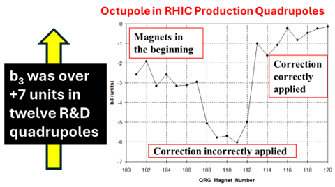
This breaks the basic quadrupole symmetry when the circular coils become a bit elliptical after collaring. As a result, a significant non-allowed octupole harmonic (over +7 units) got created, as measured in the twelve pre-production R&D quadrupole.
To fix this harmonic a simple novel solution was implemented at the start of the series production of the quadrupoles at the industry that didn’t require a change in the coil and tooling design. To compensate for this break in symmetry between the horizontal and vertical axis, another asymmetry was introduced. The coil-to-midplane gap on the horizontal and vertical axes were made different – 0.25 mm and 0.15 mm respectively. The measurements (see magnets 101-107 in figure below) indicated that this technique worked. However, the asymmetry got overcompensated in the first trial, leading to a negative value of b3. A request was made to the vendor to decrease this asymmetry by 0.025 mm which was also expected to help reduce the b5 harmonic at the injection. However, the measured change was made in the opposite direction to what was intended, and the asymmetry was increased. The measured b3 (see magnets 108-112) showed an increase in magnitude. This, and the new value of the b5 harmonic confirmed that the change was indeed in the wrong direction. The problem was corrected in the subsequent magnets and the desired harmonics were obtained (see magnets 113 and onward). Finally, we had a low-cost design with good field harmonics and a major reduction in the harmonic was achieved during the series production, without interrupting the production and without bringing in major changes.
RHIC insertion (IR) quadrupoles
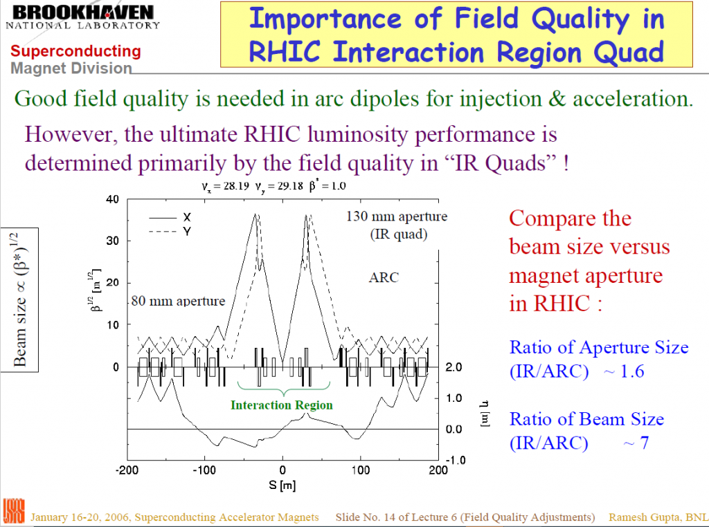
The interaction region (IR) quadrupoles for the Relativistic Heavy Ion Collider (RHIC) are the best field quality superconducting magnets ever built for any major accelerator. To increase the design luminosity of RHIC, the design beam size was made smaller at the crossing point. An unavoidable consequence of this (reference: beta*2=>beta*1 decision) was an increase in the good field aperture required in the interaction region quadrupoles. A magnet aperture larger than the design 130 mm would have caused delay and increase in cost. A tuning shim method that extended the good field region was developed. As compared to the 80 mm aperture main arc quadrupoles, the increase in beam size in these magnets is ~400%, whereas the increase in aperture is only 63%. In the high luminosity lattice configuration, the field errors in these magnets are more critical than those in the rest of the RHIC machine magnets combined.
A very high field quality, with relative errors at 2/3 of the coil radius being a few parts in 100,000 rather than a few parts in 10,00, is primarily achieved with the help of eight tuning shims that remove the residual errors from a magnet after it is built and tested. These shims overcome the limitations from the typical tolerances in parts and manufacturing. Moreover, a flexible approach allowed changes in the design parameters and facilitated using parts with significant dimensional variations while controlling cost and maintaining schedule and field quality. The RHIC magnet program also discovered that quench and thermal cycles cause small changes in magnet geometry. The ultimate field quality performance is now understood to be determined by these changes rather than the manufacturing tolerances or the measurement errors.
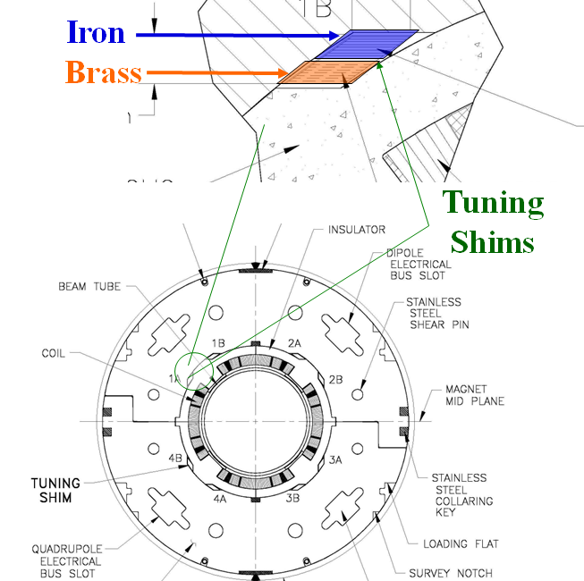
RHIC Interaction Region (IR) Quadrupole with Tuning Shims