Presentations at the bottom of the page
Introduction
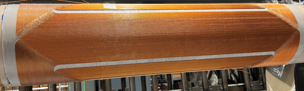
Relative loss in integral field due to ends is considerable in superconducting magnets where the length of the straight section (or body) of the magnet becomes comparable to the two ends. The optimum integral design essentially overcomes that loss by extending the body or straight section of the magnet to the whole length of the coil. Picture below shows the body of the magnet extending almost the full length as compared to that in the other designs where ends (which are not efficient in creating field) take away significant space.
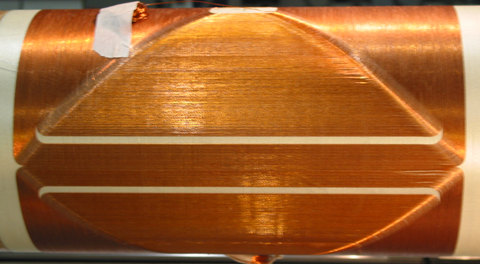
Coil of an Optimum integral design with body extending full length and essentially no loss from the ends.
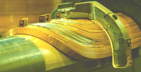
Ends of a cosine theta magnet taking away space from the length of the magnet.
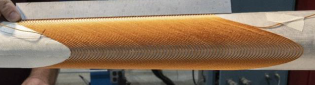
A coil based on the double helix design with ends taking away space from the length of the magnet.
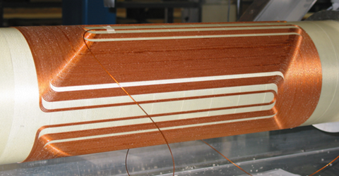
Coil based on the serpentine design showing the loss in the length from one magnet end.
Basic Principle
In conventional cosine theta design and in most other conductor dominated designs, the field in a magnet is primarily determined by the turns near the midplane (horizontal axis), while those at other angles are needed for good field quality. Cosine theta magnet design is a two-step process. In first step, the cross-section is designed to modulate the angular distribution of turns for an effective cosine theta function and in the second profile and length of the turns in the end is modulated for good field quality and lower peak field on the conductor.
The conventional conductor-dominated design involves a two-step process. First the coil cross section is optimized for the body of the magnet to create a cosine (nθ) type azimuthal current distribution:
I(θ) = Io COS(nθ)
Then, in the second step, the ends are optimized to minimize the field harmonics to practically create an integrated cosine theta current distribution in the end section with a peak field on the conductor. This 2-step optimization creates a magnet with low integral harmonics but, unfortunately, also one that has a magnetic length that is smaller than the coil length, typically by a coil diameter/(n). For the typical magnet, the main issue is that the field is primarily determined by the turns at the midplane which do not extend over the entire coil length. Also, end spacers are needed to reduce the effective current density in the ends to minimize the integrated field harmonics.
The Optimum Integral Design is a one step process where the length of the midplane turn is made essentially equal to the coil length (end-to-end) with the bend radius of the turns in the ends approaching zero. If there are no spacers in the ends or in the straight section, and if all turns are spaced equally, then the length of successive turns decreases linearly from the midplane to the pole. However, the length and distribution of turns is modulated with the help of a few spacers in the body and the ends so that the current distribution (in the integral sense) becomes proportional to cosine (nθ). The desired integral modulation is obtained with the help of a computer program after distributing a total of “N” turns in a few end blocks and/or in a few cross-section blocks. The size of the spacers between the blocks is optimized to achieve an integral distribution varying azimuthally as:
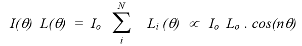
Since the cosine theta modulation is normalized to the current Io times the length Lo (Lo is the end-to-end coil length), this equation suggests that the integral field of the magnet may be closer to a typical 2D field times the mechanical length of the coil (Lo). This is a significant improvement over the designs discussed above where the loss in effective magnetic length from Lo was about a coil diameter/(n).
Current Status
A code has been developed to optimize the optimum integral design. It differs significantly from most the other 3-d codes in computing and optimizing integral harmonics and is order of magnitude faster. The approach and summary of that is described in this link and the design manual for the code in this link.
The optimum integral design opens a new window for building efficient short magnets with a dipole with length shorter than coil diameter, a quadrupole with length shorter than coil radius and sextupole with length shorter than one third of coil diameter, with the example design presented in the paper listed below.
The design is also used in the Phase I (Summary, Narrative, Presentation, Report) and Phase II STTR (Summary, Narrative, Presentations) with the Particle Beam Lasers, Inc. (PBL) and a R&D dipole B0ApF being built and tested for the Electron Ion Collider.
Selected papers, presentations, and SBIR/STTRs on the Optimum Integral Design:
- Updated Design of B0pF (with separate quadrupole and dipole windings), May 21, 2026.
- Combined Function OID B0pF (moving from PoP to optimized design), April 30, 2026.
- A Possible 4.5 K Option for B0pF with the Combined Function Optimum Integral Design, December 23, 2025.
- Combined Function Optimum Integral Design for B0pF (Risk reduction), Magnet Steering Group (MSG) meeting, December 19, 2025.
- Optimum Integral Design (OID) for Risk Reduction in B0pF, Magnet Steering Group (MSG) meeting, October 17, 2025.
- Optimum Integral Design for B0pF, October 5, 2025.
- Investigation of the Optimum Integral Design for B0pF, September 24, 2025.
- Update on the Optimum Integral Design for B0pF, August 18, 2025.
- First Look at the Optimum Integral Design for B0pF, August 14, 2025.
- A New Medium Field Superconducting Magnet for the EIC, FY25 Nuclear Physics SBIR/STTR Phase II Exchange Meeting, July 30, 2025.
- Optimum Integral Design and It’s Application to EIC Magnets, Magnet Steering Group Meeting, July 25, 2025.
- Design, Construction, and Test of a Direct Wind Dipole B0ApF based on the Optimum Integral Design (https://mt29-conf.org/), Thu-Mo-Or1-03, Boston, July 1 – 6, 2025 (abstract).
- Optimum Integral Design for EIC Dipole B1pF/B1ApF, MT29 – International Conference on Magnet Technology (https://mt29-conf.org/), Fri-Mo-Po.05-04, Boston, July 1 – 6, 2025 (poster).
- Optimum Integral Dipole B0ApF, Magnet Steering Group Meeting, June 6, 2025.
- Optimization Strategy and Code for the Optimum Integral Design, May 29, 2025 (design manual).
- Initial Investigation of Direct Wind B1pF/B1ApF (with Optimum Integral Dipole Design), February 25, 2025.
- A Proposed Value Engineering Design for B1ApF, January 7, 2025.
- A New Medium Field Superconducting Magnet for the EIC, FY24 Nuclear Physics SBIR/STTR Phase II Exchange Meeting, August 14, 2024.
- Update on Optimum Integral Design and Winding Software for Serpentine Coils, June 3, 2024.
- Optimum Integral Magnet Design (includes work performed under PBL/BNL STTR), US MDP general meeting, October 25, 2023
- A Novel, Medium-field Optimum Integral Dipole, Presented at MT28 – International Conference on Magnet Technology (https://mt28.aoscongres.com/home!en), September 14, 2023
- A new medium field superconducting magnet for the EIC, FY23 Nuclear Physics SBIR/STTR Phase II Exchange Meeting, August 15, 2023
- Optimum Integral Dipole STTR for EIC, internal presentation to BNL EIC magnet team, October 5, 2022
- STTR Phase II with Particle Beam Lasers, Inc. (PBL), “A New Medium Field Superconducting Magnet for the EIC”, (2022-ongoing), DE-SC0021578, (Summary, Narrative, Report)
- A new medium field superconducting magnet for the EIC, FY21 Phase I PI meeting, June 28, 2021
- STTR Phase I with Particle Beam Lasers, Inc., “A New Medium Field Superconducting Magnet for the EIC”, (2021, Phase I completed), DE-SC0021578, (Summary, Narrative, Report)
- R. Gupta, “Optimum Integral Design for Optimizing Field in Short Magnets”, Presented at the Applied Superconductivity Conference during October 3-8, 2004 at Jacksonville, FL, USA (2004). ****Click Here for Poster****
- R. Gupta, Optimum Integral Design for Maximizing Field in Short Magnets. Magnet Division Note No. MDN-634-37 (AM-MD-334) (February 2004). https://wpw.bnl.gov/rgupta/wp-content/uploads/sites/9/2023/03/MDN-634-37.pdf