In many low field magnets, such as for the electron accelerators, storage rings, and beam lines, one would like to obtain the maximum field integral without increasing the field. These magnets are typically room temperature iron dominated magnets where the iron pole determines the magnetic length. In such magnets, the space taken by the coil ends is not so productive, taking appreciable space without creating much field. One such example is the next generation synchrotron radiation sources, such as the NSLS-II at BNL. Increasing magnetic field is not desirable as that will increase the loss due to synchrotron radiation which is currently under 2 MeV per turn.
To overcome these challenges an innovative magnet design has been developed (see Fig. 1) where the magnetic length becomes significantly longer than the mechanical length of the iron yoke. In NSLS‑II, it allowed the length of the dipole to be reduced by 180 mm (for a total savings of ~10 meter or ~1.3% in the storage ring), without increasing the maximum field in the dipole magnet. The design is referred to here as “extended pole” design or design with a “nose”.
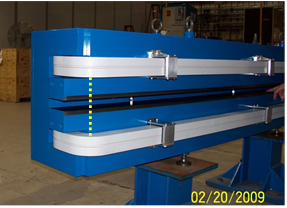
Figure 1: Prototype magnet for NSLS-II with “extended pole” or “nose”. The dotted line shows the boundary between the nose piece and the main laminations.
Magnetic models of the upper half of the yoke (with magnetic field superimposed on the iron surface) along with the upper and lower coils for three cases are shown in Figs. 2-4. Fig. 2 is for the case without any nose piece; Fig. 3 is for the nose piece of optimized length (68.5 mm) and Fig. 4 is for a nose piece which is too long. One can see that a nose piece that is too long could create a situation where the iron in nose piece may saturate. Fig. 5 shows the dipole field along the nominal beam axis from the middle of the dipole in these three cases. One can clearly see the increase in magnetic length due to a nose piece. One can also see that when the nose piece is too long the dipole field in the nose region drops. This is due to the saturating iron, as can be seen in Fig. 4 (see the place in the nose where it meets the magnet yoke).
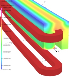
Figure 2: Magnetic model of the upper half of the yoke (and upper and lower coils) without “nose” piece.
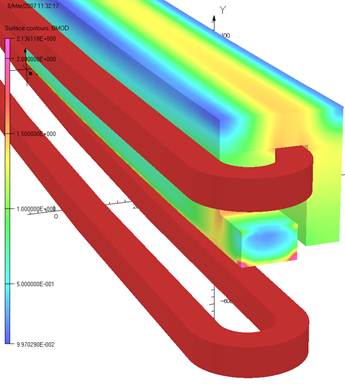
Figure 3: Magnetic model of the upper half of the yoke (and upper & lower coils) with optimized “nose” piece.
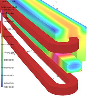
Figure 4: Magnetic model of the upper half of the yoke (and upper and lower coils) with a “nose” piece that is too long and causes saturation.
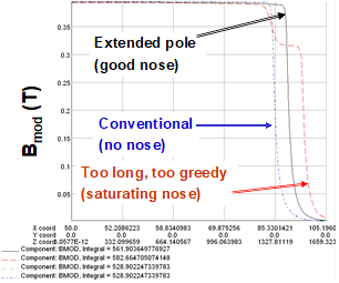
Figure 5: Dipole field (magnitude) along the beam axis from the middle of the dipole in these three cases.
The nose piece also provided a convenient way to modify the ends of the magnet. One application was to convert a magnet with parallel ends, which is generally easier to construct, to a sector magnet with a simple angular cut in the nose piece. This feature has been incorporated in a prototype NSLS-II dipole. Geometric shaping of nose piece along the beam axis could also be used to adjust the field fall-off to obtain a better match between the end profiles of 35 mm and 90 mm aperture dipoles.